

Article: Automated testing of LED blink interfaces as part of software/hardware testing
14/08/2024A case study on automated testing of LED blink interfaces as part of software/hardware testing, conducted during a student internship project.
During career fairs and student meetings, we’re often asked about the kinds of projects our interns work on. This question is important because it relates to developing technical competence and engaging interns in hands-on work that will prepare them for further professions.
In the article below, you’ll find a case study prepared by our intern, Piotr Korman. The project involved creating a hardware interface using a phototransistor to convert light intensity into voltage and communicating this data to a PC via the RS232 interface. The software solution decoded various blink patterns to determine the device’s status with high accuracy.
Automated testing of LED blink interfaces as part of software/hardware testing
Introduction of the problem
When thinking of Software Testing, we usually think about applications (be it for Web, Mobile, or Desktop). However, when working in the embedded branch of software development, there is also something called a device test, where the developed software is tested running on real hardware. This test phase requires testing of (among other aspects) all the accessible interfaces, including the most unusual – “non-software” ones.
Industrial devices usually contain a very crude visual interface. It’s often not a display, but a simple LED turning on and off for specific time periods – special blink codes. That interface is usually used to indicate basic problems of the device – missing software part (making it unable to boot) or a problem in the hardware. The inability to boot is especially difficult to diagnose because usually all other interfaces (CAN, Ethernet, a regular graphical screen) get initialized later in the start-up process, so they cannot be used to inform users what the issue is. That’s why designers put such a LED into the final device and why it gets implemented in the firmware (usually) – to be able to diagnose the problem quickly at the installation place.
But how does this affect testing? For manual testing, the tester can look at the LED, count the blinks, and distinguish long and short pulses or the lack of them. It’s quite imprecise, but sufficient in most cases. It gets more complicated if we want to implement such a test in an automated script. We need to design an interface to connect the LED with our test automation system (PC). In most cases, we don’t want to connect electrically to the device since it might affect its performance. We need to find a way to readout the intensity of light on the PC and decode the blink pulses.
Hardware part of the solution
This issue can be split into two parts. How to convert the blinking light into something useful in a test and how to communicate it to the PC. A simple phototransistor can be used to convert light intensity to a voltage. For communication, the RS232 interface has been used. To be more specific, the control line DCD has been used, because of its non-synchronous nature. A hardware RS232 port in a PC can be used, or a simple USB to RS232 converter can be added if the amount of ports is insufficient.

Figure 1 Electrical diagram of the light receiving component.
The receiving of the light signal has been implemented using a phototransistor with the addition of several additional components to condition the signal. Here it is important to know that the RS232 interface operates in a not obvious manner: a high signal means -15…-3V and low means +3..+15V. To avoid using an external power supply, the RTS and DTR control lines have been used to get a signal in the correct voltage ranges.
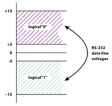
Figure 2 Logical voltage ranges of an RS-232 interface.
In the end, we’ve got a simple converter from light intensity to a series of 1s and 0s on the DCD line of the RS-232 interface.
Software part of the solution
The second obstacle is to implement a piece of software decoding the blinks. This might sound trivial, but in our case, there were 3 kinds of possible blinks: short <0,25s, long >=0,25s but <0,5s, and very long >1s. In comparison, Morse code has only 2 possible pulse types (short “dot” and long “dash”).
To analyze the received pulses, we selected the following criteria:
- Amount of rising edges,
- Positive pulse length,
- Comparison of the location of the high pulses to a template.
Using these metrics, we calculate a statistical probability to determine how certain we are that we have observed the decoded state.
It is also not easy to find the start of the cycle of the pulses. In this case, every second rising edge triggers a fixed time recording and is immediately decoded. This assures the decoded state is at most 2 cycles old.
Summary
Overall, the implemented solution delivers excellent results and is a key component in one of the test systems. The achieved certainty of the decoded state is always higher than 90%. The implemented solution shows, that sometimes we can avoid using expensive DAQ cards or full systems. Sometimes a crude interface is sufficient to achieve acceptable results.
This project is just one of many that our interns work on. Engaging in these projects provides them with essential practical experience in both hardware and software engineering.
Take a look at our previous articles.